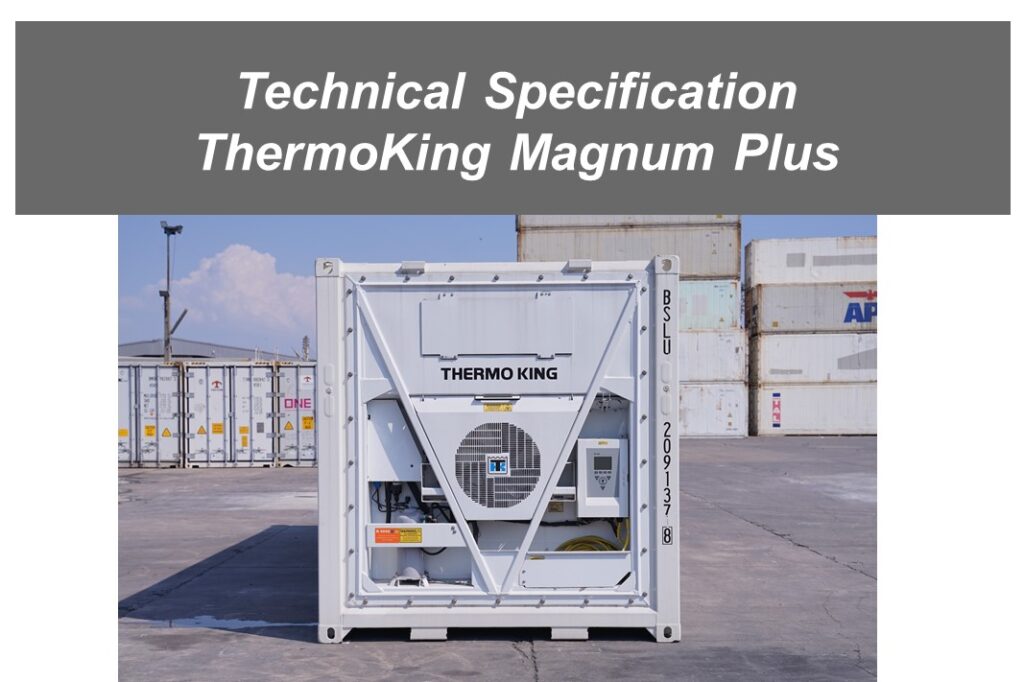
Technical Specification Refrigerated Container ISO 1CC-20’x8’x8’6″ MGSS REEFER – Polyurethane insulation (By CP Blowing Agent)– Roof and side panel MGSS– Front and Rearend frame SPA-H– Floor rail aluminum– Lining : Side & door BN4 or ZPHD4Roof pre-painted aluminum sheet– Top & bottom rail SPA-H– Corrugated base SPA-H– Scuff Liner Aluminum Operational Environment The container is designed and manufactured for the carriage of refrigerated (frozen & chilled) foodstuffs and general cargo by land (on road or rail) and by sea (above or below deck) throughout the world with external temperature ranging from -40°C to +60°C without effect on the container strength and water-tightness. A mechanical refrigeration unit of a “one piece frame type” will be fitted to the front end frame. The container is designed with a refrigeration unit to maintain the inside space temperature at -40°C in ambient temperature up t +50°C Handling he container is constructed to be capable of being handled without any permanent deformation, which will render it unsuitable for use or any other abnormality during the following conditions : TransportationThe container is constructed to be suitable for transportation for the following modes without any permanent deformation which will render the container unsuitable to use or any abnormality. Dimensions and Ratings External dimension Length 6,058 mm (0, -6) Width 2,438 mm (0, -5) Height 2,591 mm (0, -5) Internal dimension Length 5,456 mm (0, -12) Width 2,290 mm (0, -10) Height 2,276 mm (0, -10) Cargo access height 2,224 mm (0, -10) Door Opening Width 2,294 mm (0, -5) Height – at sill 2,264 mm (0, -5) Forklift Pocket Width Height 115 mm Centre distance 2,050 mm Inside Cubic Capacity 28.4 m3 (1,005 cu.ft.) Rating Insulated Box : Max. Gross Weight 30,480 Kg 67,200 lb. Tare weigh (excluding Reefer Unit) 2,830 kg±2% 5,400 lb. With CARRIER Prime line Reefer Unit : Tare weight (Include Reefer Unit : 380 kg) 2,830 kg±2% 6,240 lb. Payload 27,650 kg 60,960 lb. With TK Magnum Plus Reefer Unit : Tare weight (Include Reefer Unit : 380 kg) 2,830 kg±2% 6,240 lb. Payload 27,650 kg 60,960 lb. Insulation (Polyurethane foam with Cyclopentane (non‐CFC) blowing agent) Item Thickness Core Density Roof 80 mm. 40‐45kg/m3 Side Walls 63.5 mm 45‐50kg/m3 Door Panels 74 mm 50‐55kg/m3 Floor 76/111 mm 45‐50kg/m3 Corner 40‐45kg/m3 Heat leakage value Umax = 25 kcal/deg.c.hr at 20°C(293k) mean wall temp. Air leakage Qmax = 3 cu.m/hr measured at 25.4±1mm WPG inside. Materials Part Materials Front & rear corner post Corten Steel grade SPA-H or equivalent Front header & sill Rear header & sill Forklift pocket Top & bottom side rail Front & rear double plate Side post Subfloor Side, roof and door panel Recessed conrugated stainless steel (MGSS) Clip on device angle Hinge lug Roof bow Side stringer Generator fitting nut Stainless Steel SUS304 Hinge pin Data plate Part Materials Side lining Stainless Steel BN4 or APHD4 Door lining Corner fitting Casting steel SCW480 Roof lining Coated Aluminium AA5052-H44/H46 Floor rail & floor bow Aluminium Extrusions AA6061-T6 Roof stringer Aluminium Extrusions AA6063-T5 Rear corner post inner(flat bar) Hot Rolled Steel SM490A Door hinge Structure Steel SS400 (HDG) Door holder Stainless steel with Plastic Locking rod Plain Carbon Structural Steel Q235B or equivalent Insulation tape Electrolytic buffer of P.E. or P.V.C. Foam tape Adhesive of P.V.C Insulation foam 1) Rigid polyurethane foam 2) Blowing agent : CP Exposed sealer MS (inner) FDA compliant Silicone (outer) Hidden sealer Butyl Material Yield point (N/sq.mm) Tensile strength (N/sq.mm) SPA‐H 345 485 SS400 245 400 SM490A 280 490 MGSS 195 360 SUS304 205 520 BN4 250 600 ZPHD4 275 650 SCW480 275 490 AA5052‐H44 130 205 AA5052‐H46 180 235 AA6063‐T5 130 175 AA6061‐T6 240 260 Forged steel 270 450 Q235B 235 440 The metallic material thickness tolerance shall comply with JIS relevant standard. General constructionThe container is constructed of steel parts, which are rear and front frame, insulated side with corrugated outer panel and inner lining, insulated base with aluminium ”T” section floor rail and corrugation subfloor, insulated roof is constructed of outer panels and inner lining with corrugations, insulated door with outer panel and corrugated inner lining, and ISO corner fittings. Refrigeration unit will be installed to the front end frame. Base frameThe base frame is composed of corrugation type steel base frame and “T” section aluminium floor rail with Insulation polyurethane. Forklift pocket: Two pieces of 4.0mm thick pressed hat section with 6.0mm lower plate. Subfloor: 1.6mm thick SPA‐H corrugated panel welded to the bottom side rail.Load transfer member: Three (3) 3.0mm thick rectangular tube. Bottom side rail: 4.0mm thick upper with 3.0mm reinforcement angle, and 4.0mm lower cold rolled steel. Welded 4.0mm thick reinforcement plate between bottom side rails and fittings. FloorFloor board: 40mm high and 63.5mm spaced aluminium extruded “T” section. Floor bow: 4 pieces of Aluminium extruded “I” section floor bows shall be stitch welded to the underside of floor board. Floor filler: Seven (7) pieces of PE fillers located between T‐floor and base panel near door sill. Lashing bar: Aluminium lashing bar (Φ18) is welded on the floor, 2pcs per side. Front end frameFront end frame is composed of steel members, which is constructed so that refrigerating unit and generator device can be fitted. Front top rail: 4.0mm thick pressed profile. Front bottom rail: Welded construction with 4.0mm thick pressed profile with three (3) pieces of 4.0mm thick stiffeners. Corner post: Welded construction with 6.0mm thick outer and 3.0mm thick inner pressed profile. Double plate: 4.0mm thick rectangular plates. Rear end frameRear end frame is composed of steel frame members, which is constructed so that a set of door can be fitted. Door header: Welded construction with 4.0mm thick outer and 4.0mm thick inner, and 4 pieces of 4.0mm vertical gusset plates welded behind of cam keepers. Door sill: Welded construction with 6.0mm thick outer, 4.0mm thick inner angle plate, 4.0 thick horizontal support plate and 4 pieces of 4.0mm vertical gusset plates welded behind of cam keepers. The lower flange of the sill near to corner fitting is provided with channel section cut‐outs for damage protection. Corner post: Welded construction with 6.0mm